If you’re not interested on the background to this fix/mod, skip past the winding paragraphs, down to the guide.
This is my first original mod/fix done back in 2006. I was pretty new to console modding, and electronics in general. I got a free Sega Genesis from a family friend, and was extremely disappointed when I saw the quality of the composite video output. There were vertical lines in the background at specific points much like the NES model 2 composite video but much worse. It was hard to play Toejam & Earl when all of Toejam’s limbs were connected! No wonder I was so envious of my neighbor when he got a Super Nintendo for Christmas ’91 and I got a Sega Genesis!
As an aside, I loved my Genesis, and had asked for it by name. The lack of games was very frustrating to a 7 year old though. My mother took me to the rental place in the drug store every Thursday. Every week they’d have more cool SNES games, but maybe one or two new sports games for the Genesis (I hated sports as a kid! Video games were my escape from sports and all the athletic kids. The last thing a budding nerd wanted to do was escape into the mystical world of “PGA Tour III”!).
Only the Genesis with the KA2195D video encoder have this issue from what I understand (A list of the different hardware on different board revisions of the Genesis and their strengths and weaknesses). It’s my impression that the KA2195D video encoder is not a bad encoder, and it’s not the real issue. From the research I did back in the day, my guess is poor board layout that lead to lots of noise, possibly on the +5v rail, which lead to a noisy 3.58MHz clock to the encoder. The fact that the vertical lines were at specified points on the screen at different points on the refresh rate on the TV lead me to suspect the clock signal since the lines were so consistent and stable. Random noise from something else would have induced well, random noise on the video. I took some o-scope video of the signal back then and it was pretty rough. There was some high frequency noise.
I solidified my noisy board theory recently when I did the ol’ Crystal Clear Audio Mod (If you haven’t read about it, Google it or read my next blog entry… whenever that is [or buy my CCAM Genesis on Ebay]. This blogging stuff has been a big enough pain in the ass already). Without a separate voltage regulator on your CCAM, there is some really bad buzzing on the audio output. Using a separate 7805 eliminates this noise.
I looked at the datasheet for clues on how the chip was supposed to be interfaced and found the clock input. I decided to use a crystal can oscillator at 3.58 MHz. I cut the original clock line and fed the can oscillator to pin 6. Voila! beautiful, flawless composite video (As beautiful and flawless as composite can be)! I posted on the Gamesx forum about this back then. Someone said they tried to build their own crystal oscillator circuit, as per the diagram in the datasheet, and it didn’t work right. The Quartz Crystal Oscillator, often times called a Can Oscillator, is what I used and it does work. Perhaps the can oscillator has an input voltage filter on the PCB inside it. Maybe a ceramic resonator would work too, but who cares? We know what works!
I submitted this to the guy at www.gamesx.com (Pretty much the original source for console mods) and he said he’d post it, but never did. So without further interruption…
Tutorial!!!!!!!!!!!!!!!!!!!!!!!!!!!!!!!!:
This tutorial will show you how to remove the vertical lines that plague the NTSC Model 2 Sega Genesis version. It will show you how to feed a new clock signal to the video encoder chip to clean up the composite video.
As with any hardware modification, your results may vary, and I’m not responsible for damages or unsatisfactory results. Please make sure you are skilled in soldering before you attempt this mod!

|
The Sega Genesis Model 2 is the second version of the original Sega Genesis. It was made to be smaller with a sleeker design. |
The things you will need are:
- Soldering iron with solder
- Exacto Knife
- 3.58 MHz Can Oscillator
- Philips Screwdriver
- Some 22 gauge or smaller wire
Fortunately for us the Sega isn’t fastened together with funky security screws. All you need is a Philips head screwdriver to unscrew the 4 screws underneath the case. After that, lift the top of the case off and set it aside.
Now you should see the large metal RF shield encasing. Look for the 8 screws lining the outer edge of the board that hold the shielding down. Unscrew all 8, lift the shielding up and set it aside.
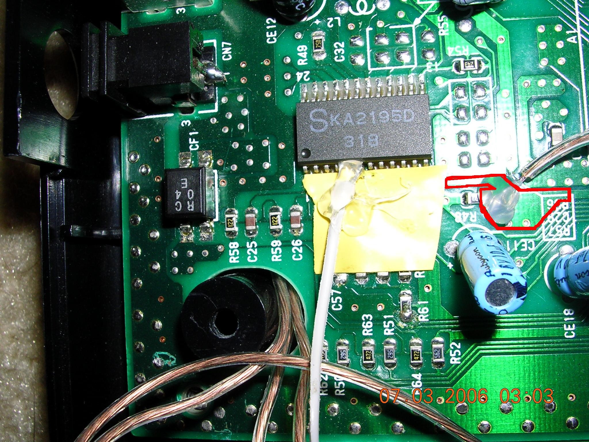
Now examine the circuit board, and find a chip in the top left corner labeled KA2195D.

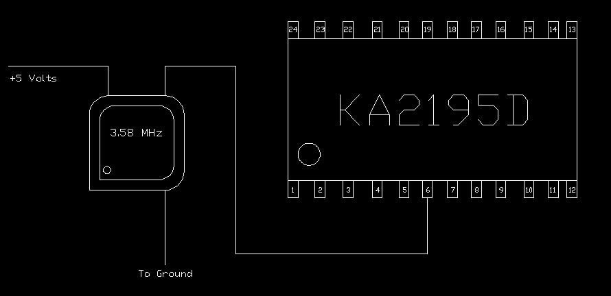
This is the video encoder chip we’ll be dealing with. Find a nice spot to put your oscillator where the console’s case can still close and the oscillator won’t touch any exposed wires or pins. Using the diagram below, locate pin 6 of the chip (start counting at the small circle indention in the bottom left of the chip. This indicates pin 1). This is the pin we’ll feed the output of the oscillator to.
Before you can solder the new clock signal to pin 6, you must sever the pin from its original clock by lifting it off the board. To do this, after tinning your soldering iron, touch it to the pin to melt the solder. Then quickly but carefully slide the exacto knife blade underneath the pin, and gently lift.
Now that it is lifted you can solder the wire from the output pin of the oscillator (the pin diagonally from the little black dot on the oscillator) to the now lifted pin 6. Be very careful when soldering to this pin, it can snap off or cause heat damage to the chip if you leave the iron on it too long.
After it is soldered, I usually surround the connection with hot glue (update 2013: JB Weld works way better and is permanent) to help keep the pin safe from vibration (dropping your system) or if I were to accidentally pull on the wire.
Now that the pin is connected to the new clock signal, you must provide power to the oscillator. You can use the picture below to find a place to solder the +5v pin of the oscillator to. Anywhere inside the red box is appropriate because it provides +5v to the chip through pins 12 and 19 only when the system is on. There are a few via holes to solder a wire to in the red box, or to the soldering point on the one side of the black surface mount resistor (R48 in the picture).
The ground for the oscillator can be found all around the outside of the board. On pins 1 and 24, or you could even tie it down to one of the screws that hold down the RF shield, but I recommend soldering it somewhere.
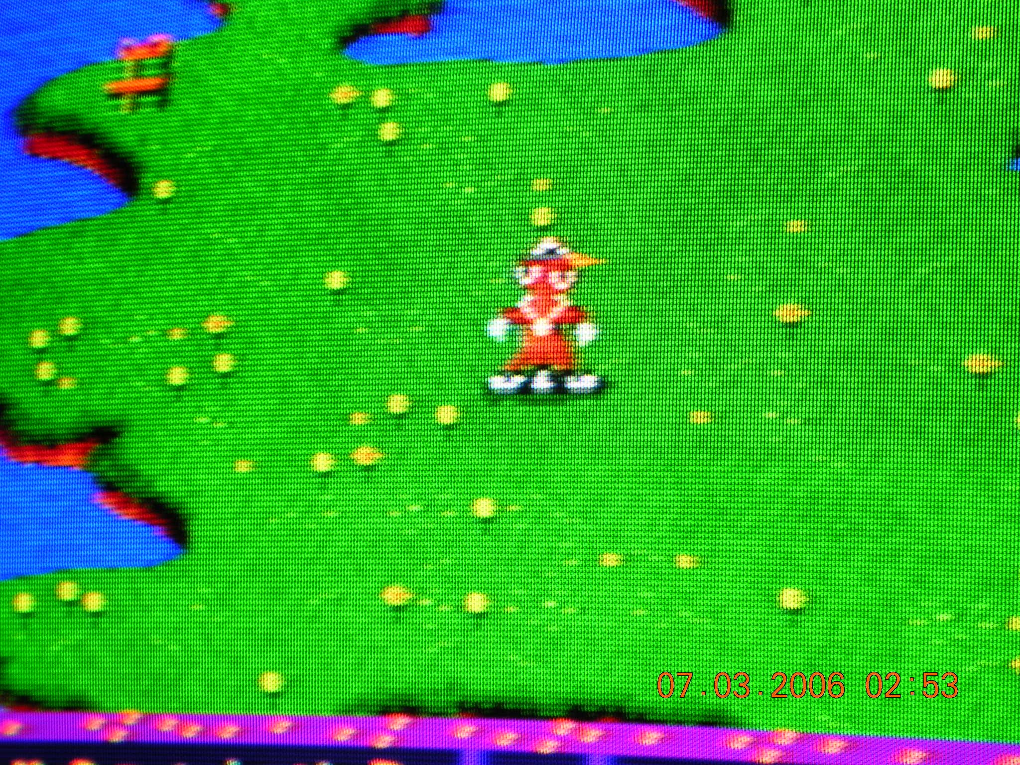
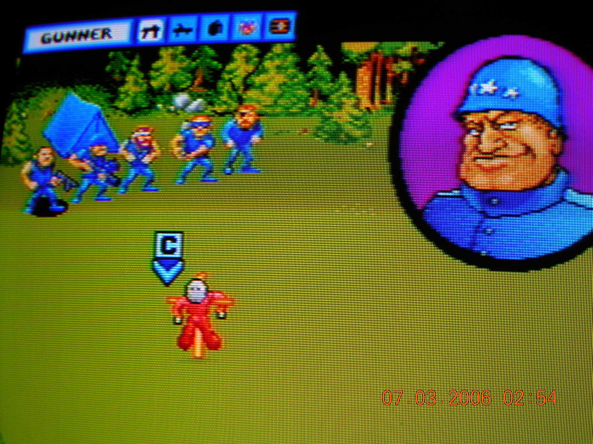
And that’s it! Boot up your system with your favorite game and enjoy the crisp graphics. If you’ve played on the system long enough with the lines, you will notice a great difference. Here are some after pictures (there are no before pictures 😦 ) :


Hey excellent tutorial, where did you purchase the 3.58 MHz Can Oscillator?
I actually found it at a local electronics store in Dallas. You can find them on Digi-Key and Mouser. Looks like digi-key has a 3.584 Mhz that’s a through hole. The 3.58 are surface mount.
I have been trying to find information on this fix for a long time. There is no place on the internet that shows this fix. I think it is important because there are so many Genesis plagued by this issue. I myself have had maybe four that possessed it. The closest thing I have found to this is doing an RGB setup but I knew it wasnt going to fix it like this will. I am glad you finally figured it out. I am going to do the fix as soon as I can find the 3.58 MHz can oscillator online. My only question is exactly where did you solder the 5v power source to the motherboard, I couldnt really understand the directions, I know it says “Anywhere in the red box” but that isnt telling me enough. Also, im not sure exactly what the can oscillator looks like and if there are different types. I have done tube amp repairs but I dont know alot of theory so I need pretty exact instructions. Thank you for this
Sorry for the late reply. I soldered the power wire to the via holes (the little solder lumps) inside the red box. You could also scrape a little enamel away from the board and solder to the copper underneath.
If you still can’t find a place, solder a wire directly to the output line of the 7805 voltage regulator which will be 5v.
This is what a typical “can” oscillator looks like (it’s actually known as just an “oscillator”, but the can refers to the oscillators with the specific metal packaging): http://www.amazon.com/MHz-Full-Can-Crystal-Oscillator/dp/B00B886YGC
They come in a square package too. You can see mine in the picture.